While I was working as an embedded systems engineer, I was a member of the team that developed v2 of the Micro Air Data Computer (uADC). During beta testing of the v2 uADC we encountered a bug involving clock skew while the aircraft was in flight.
Background
The uADC is typically mounted on UAVs or other aircraft and is used to measure flight characteristics like:
- angle of attack
- angle of sideslip
- altitude
- ambient pressure
- ambient temperature
In addition, the uADC has integrated GPS/INS functionality with each sample containing:
- latitude
- longitude
- velocity vector
- acceleration vector
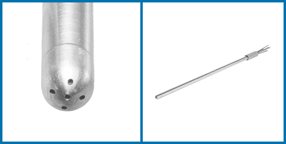
Every 10 milliseconds the uADC samples pressures from each of the five ports on its probe and uses these pressures to compute the flight characteristics. The uADC outputs samples via the serial port and logs to onboard USB flash memory.
The Issue
A customer was collecting meteorological data in the Arctic via high altitude UAV flights and reported an anomaly in their logs: they had more samples than expected for their flight time.
The Investigation
While reviewing the logs, we noticed that data from the GPS was updating at irregular intervals.
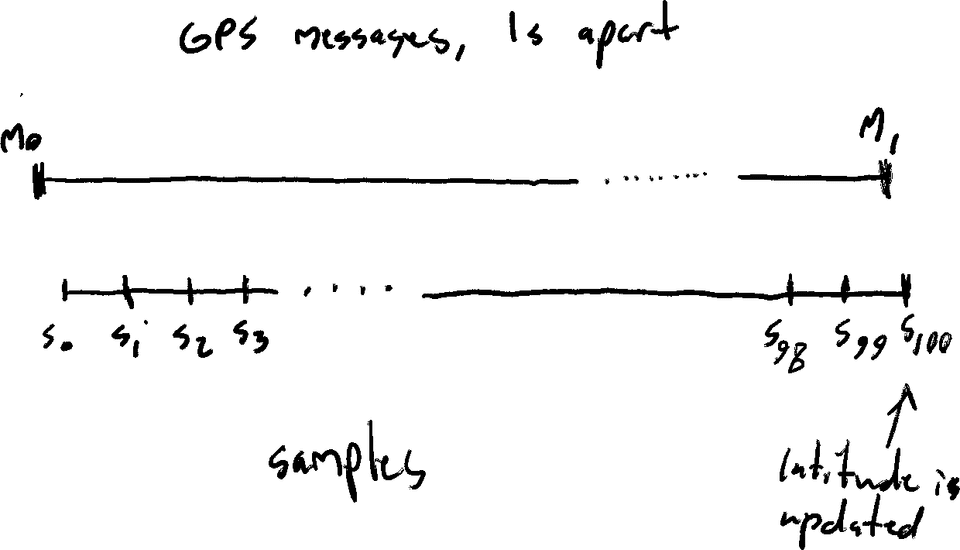
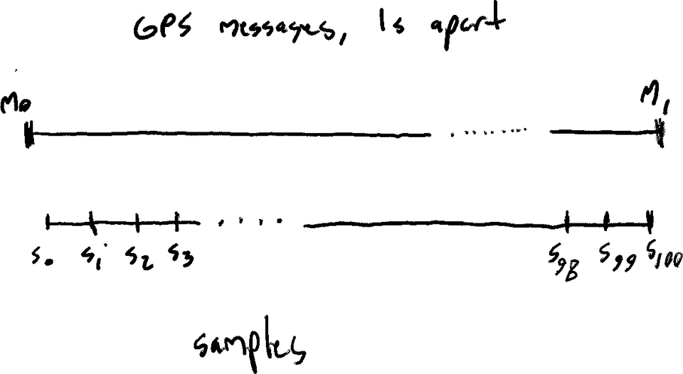
Since GPS messages are received once per second, latitude and longitude values are only updated 1 out of every 100 samples.
When the uADC boots, the timestamp from the first GPS message received is used to initialize the uADC’s clock. Afterwards, the sampling process begins and the clock is incremented every millisecond by a timer interrupt (giving the uADC’s clock 1ms precision).
Expected Timing
Because the GPS messages contain timestamps with single-second precision, we initialize the uADC’s clock’s millisecond value to 0. We expected a sample to be triggered immediately after receiving a GPS message at the start of a new second and we expected the latitude and longitude to be updated at the new second boundary.
Actual Timing
Instead, we noticed that as the flight time increased latitude and longitude started being updated at irregular timestamps. After further investigation, we noticed there were 100 samples in between GPS updates in some cases (instead of the 99 expected).
Why were extra samples being logged?
We knew that the GPS updates happen at exactly 1 second intervals, as GPS messages are received at extremely precise times. If there are 100 samples in between GPS updates (instead of the expected 99) it must be because we are sampling too frequently.
The same timer interrupt that drives the uADC’s clock also triggers the sampling process. Because there were too many samples in the log, we deduced that the timer interrupt must have executed too frequently.
Why was the timer interrupt firing too frequently?
A timer interrupt is initialized to periodically execute after a certain number of CPU cycles. We wanted our interrupt to fire every millisecond. Our CPU was clocked at 60 MHz, so we initialized the interrupt to fire every 60,000 CPU cycles.
If our interrupt was firing too frequently, our CPU must be overclocked.
Approximating our actual CPU frequency
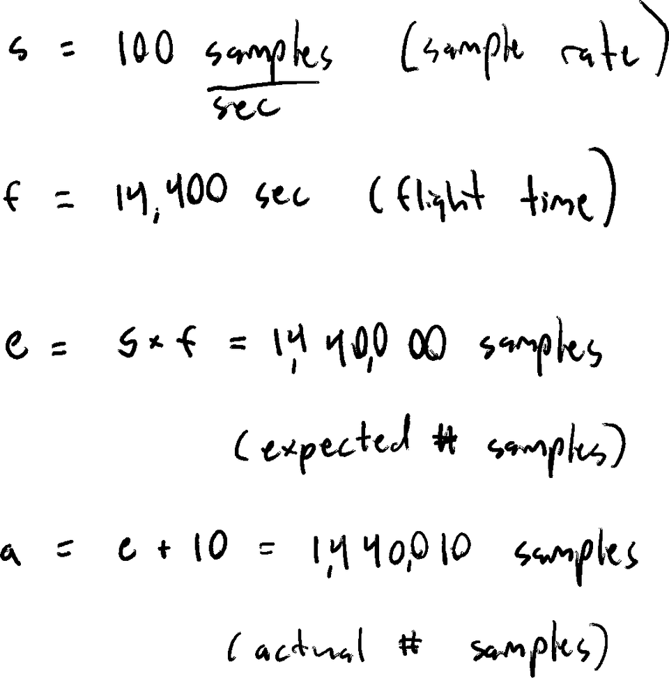
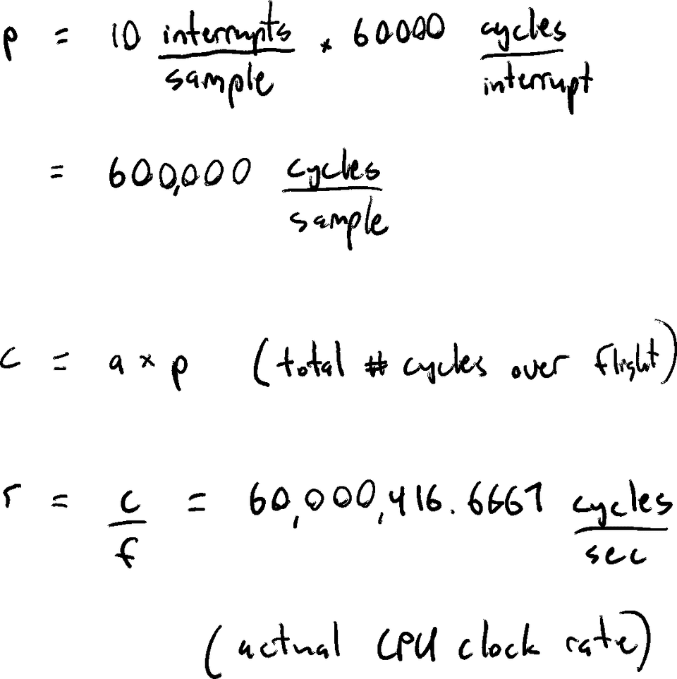
Assume the customer’s flight time was exactly four hours and 10 extra samples were logged over their flight.
Because we had the customer’s logged data and their flight time, we could use the number of logged samples to estimate the frequency our CPU’s clock was actually running at.
By observing that a sample should be triggered every 600,000 CPU cycles, we can approximate the total number of CPU cycles over our flight by multiplying 600,000 with the number of samples logged. We can then divide the total number of CPU cycles with our flight time to estimate our CPU’s actual clock frequency.
Is the quartz crystal’s resonance frequency changing?
The CPU clock is driven by a quartz crystal’s resonance frequency. The resonance frequency of a quartz crystal can increase with temperature. Is it possible our crystal’s frequency is changing?
Because the uADC has an 8 MHz crystal, to get our clock rate of 60 MHz we multiply the crystal’s resonance frequency by 10, divide by 4, and multiply by 3.
Using our example above, given that our CPU only had an extra ~417 cycles every second, our quartz crystal only needed to generate an extra 417 / 10 * 4 / 3 = 55.6 cycles per second.
We checked the spec sheet for the crystal and this amount of change was indeed possible as the temperature increased.
Our hypothesis
Since the customer’s UAV was flying at a high altitude where the atmosphere was less dense, we believe that:
- there were less air molecules to conduct the heat away
- causing our electronics to overheat
- causing the quartz crystal’s resonance frequency to increase
- causing the CPU to become overclocked
- and the timer interrupt to fire too frequently
- causing too many samples to be logged for the customer’s flight time.
Correcting the Customer’s Data
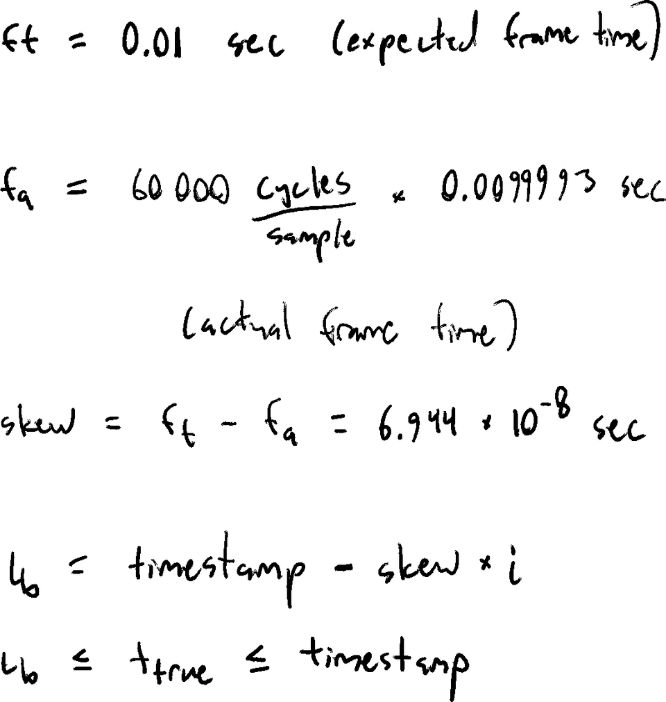
Luckily, the customer did not need sampling precisely at 100 Hz and only required corrected timestamps.
Since our clock is ticking slightly fast, after we first initialize the clock the error in the samples timestamps will be relatively small, but the longer the flight continues the error will get progressively worse.
If we assume each sample’s frame time is slightly shorter than the expected 10 ms and assume our error accumulates monotonically, we can define bounds for each sample’s true timestamp.
The Solution
The long-term solution was to calibrate the timer interrupt based on the number of CPU cycles between received GPS messages.
